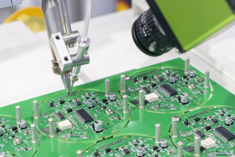
Electronics design is constantly evolving due to new technology innovations. Professionals constantly need to keep up with this change to be competitive. Printed circuit board (PCB) designers are no different, constantly finding new ways of designing PCBs with the latest tools and techniques.
This post is an introduction about how designers can improve the design of their PCBs by considering the following four concepts: use best practices, ease-of-use, maintainability, and modularity & extensibility. You can use the software you are comfortable with, or you can see if your manufacturer has preferred software. Check out different manufacturers, like Advanced Circuits, for more information on production.

Use Large-Scale Components
Before the proliferation of large-scale libraries, many designers used parts that were 2 to 3 times the size of other components on the board. With these larger parts, you could make it much easier to identify their positions on the board. Although you might not use them for all designs, using large-scale components may be a good way to make your design easier to print—particularly if you are dealing with complex designs where it’s hard to find one component at a time.
Create a High-Altitude Layer
For those who have never heard of this technique, a high-altitude layer will help you to match the components on your boards to those of your schematic. If you’re designing a circuit that doesn’t use surface mount components, you can certainly skip this step, but it can certainly help if there’s a circuit that has a lot of surface mount devices on it.
Create a Reference Layer
If you have a schematic for a PCB designed by someone else, then creating a reference layer will help you match the component positions on the schematic to those on your board. You can also include other layers in your design that have been created from the schematic—especially if they have been edited from the original schematic, such as traces and vias.
Use Callout Buttons
Once you have created your layers from the schematic, you can click on the callout command. It will allow you to add components from the schematic to your board to correspond with their positions on the schematic.
Use a Different Layer for Different Types of Components
By separating different types of components onto different layers, then you can use that layer to quickly find a particular type of component in a complex design. If you lose contact (or a wire), finding that component in the layers can be quite easy.
Use Large-Scale Component Libraries
If you’re working with a complex board, then it’s likely that some components on it aren’t found in common libraries. By using large-scale component libraries, you will be able to show where those components are located on your board so that you don’t have to waste time searching for them.
Use Layers from Other Boards
If you have a board that has been designed by someone else, then you can either use the layers from that board or use it as a reference to compare to your board. Either way, you will be able to make any changes to your design much quicker.
Use Display Layers for Strip Boards
When working with strip boards, the components must be placed in their proper positions for the stripboard to work correctly. Using wire-wrap tools to create the board, you must select the wire-wrap layer to place the components on the correct layer.
The methods for improving the design of your PCBs are as numerous as those who design them. By taking these recommendations into account, you will improve your designs and make them easier to manage.